
Meter Tampering Simulation Load Bank Test | Resistive & Reactive RLC AC Load Bank:electric meter current bypass RLC load bank test simulation, electric meter missing neutral/current reversal/neutral distrubance RLC load bank test simulation
Why need load bank testing
It is really critical that your standby power system say UPS(uninterrupted power supply), battery bank, generator, transformers, inverter etc working in good condition if switched to be loaded when the main power supply in maintenance procedure or stop abnormally. Downtime could be reduced by regular maintenance and thorough inspections which are the key to power supply systems maintenance.
Critical power backup equipment like UPS System and generator which especially located in harsh, dusty or corrosive environment will fail without proper preventative maintenance. JUNXY provides a whole range of custom preventative maintenance products solutions for UPS systems and generators and many more to ensure constant uptime for your power systems and make you prepared for anything.
Load banks help highlight a large range of faults on the equipment it tests. The first objective when testing with an electric bank is to ensure your equipment’s power supply is reliable. The underlying question that needs answering is whether your equipment will have sufficient power supply to ensure uninterrupted operational performance. The load bank also tests that the equipment is not faulty, that there are no faults in construction, that the aging of the equipment is in line with expectations, that the components are reliable and that there are no pending breakdowns or early signs of wear and tear. The load bank also ensures that the product delivers power conform to its specification.
Resistive & reactive load banks are able mimic motor loads and electromagnetic devices within a power system as well as purely resistive loads by offering the ability to set a specific power factor (pf). Many backup generators and turbines are rated at 0.7, 0.8 or 0.85 power factor and need to be commissioned at nameplate capacity using a combination of resistive and reactive load to fully qualify their operating capability. Using a resistive & reactive load bank enables comprehensive testing from a single unit. JUNXY has an extensive range of resistive & reactive load banks to simulate these types of loads on a power source and the transformers, relays, and switches which will distribute the power throughout your facility.
Inductive & capacitive load banks are reactive only and must be used in combination with a resistive load bank to provide the desired load profile to test a power system. Reactive loads banks can provide either a leading power factor (Capacitive) or lagging power factor (Inductive).
JUNXY RLC load banks are mostly used for inverter anti-islanding test experiments which meets the PV & grid inverter testing requirements for islanding prevention detection, work efficiency test, overload protection test, over-current protection test, power factor test, grid current harmonic test, resonance point test, and so on. Both Leading power factor (Capacitive) and lagging power factor (Inductive) could be available with JUNXY series RLC AC load banks.
JUNXY series AC load bank testing offers you whole solutions of predictive failure analysis for UPS(uninterrupted power supply), generator, transformers, PV system, inverter etc, to validate the condition and output of such power systems comprehensively, which includes (click to view more):
| Technical Specifications | |
|---|---|
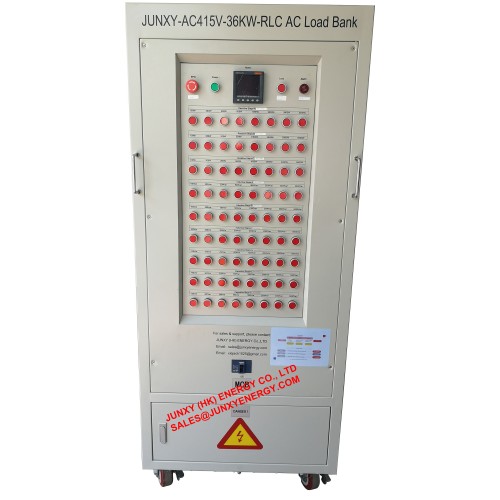
| Model | JUNXY-AC415V-36KW-RLC AC Load Bank |
| Load Element | Resistor, inductor and capacitor |
| Load Voltage | AC415V 3P4W & AC240V 1P2W |
| Frequency | 50Hz |
| 3 Phase Load Power | R=36KW(12KW per phase) L=36KVar(12KVar per phase) C=36KVar(12KVar per phase) |
| Load Steps Per Phase | Resistive load steps per phase: 100W-12KW adjustable Resistive load steps for phase A/B/C(8 steps per phase): 100W, 200W, 200W, 500W, 1KW, 2KW, 3KW, 5KW Inductive load steps per phase: 100Var-12KVar adjustable Inductive load steps for phase A/B/C(8 steps per phase): 100Var, 200Var, 200Var, 500Var, 1KVar, 2KVar, 3KVar, 5KVar Capacitive load steps per phase: 100Var-12KVar adjustable Capacitive load steps for phase A/B/C(8 steps per phase): 100Var, 200Var, 200Var, 500Var, 1KVar, 2KVar, 3KVar, 5KVar |
| Power Factor | Leading and lagging power factor 0-1.0 adjustable |
| Load Accuracy | Resistor/capacitor: ±5%, Inductor: ±5% |
| Digital Meter | voltage, current, active power, reactive power, apparent power, power factor, energy, frequency |
| Mains Voltage | 240V 50Hz, single phase |
| Control Modes | Local control panel by push buttons |
| Load Input Wire Connections | Copper bus bar for wire connections |
| Insulation Class | F |
| Protection Level | IP20(indoor use) |
| Fan Noise | 75dB |
| Cooling Mode | Force-air vertical cooling, by axial-flow fans. |
| Work Mode | Continuous work |
| Protections | Overheating/Buzzer alarm, Overheating/Over current, over voltage, over load protection, emergency stop button |
| Dimension | 750*1100*1850mm |
| Weight | Around 480kg |
| Mobility | 4 wheels |