
JUNXY series AC/DC load banks are for many power supplies load bank testing, to ensure that the standby power supply system say UPS(uninterrupted power supply), battery bank, generator, transformers, inverter etc which especially located in harsh, dusty or corrosive environment working in good condition, when you need them most, if switched to be loaded when the main power supply in maintenance procedure or stop abnormally.
The AC/DC load bank loading test preventative maintenance of such power supply systems could free you from power supply failure, to ensure constant uptime for your power systems and make you prepared for anything. Downtime could also be reduced by regular maintenance and thorough inspections which are the key to power supply systems maintenance.
Load bank testing could help highlight a large range of faults on the power supply systems it test. The first goal achieved when testing with JUNXY AC/DC load bank is to ensure your power supply system is reliable or not by validating the power systems’ outputs to its technical specifications. The underlying question that JUNXY series AC/DC load bank could answer you is--“how is my power supply systems constant uptime(technical performance) ?” The load bank also tests that the power supply system is not faulty, no faults in construction and components reliable, that the aging of the power supply system is in line with expectations and that there are no pending breakdowns or early signs of wear and tear.
The ATS load bank could do adjustable load current/voltage/power factor to achieve the ATS testing goal.
| Technical Specifications | ||||||||||||
|---|---|---|---|---|---|---|---|---|---|---|---|---|
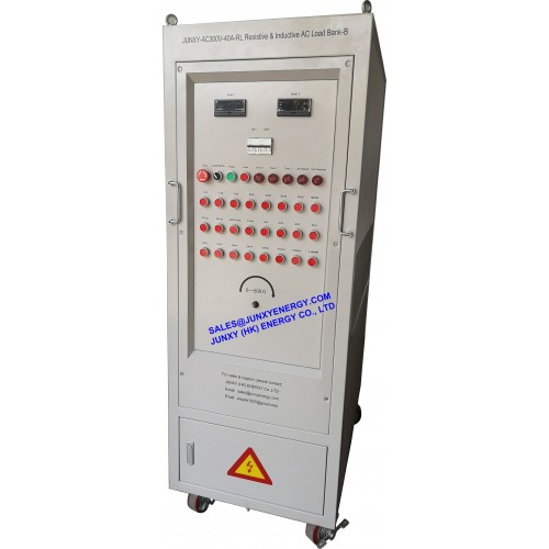
| Model | JUNXY-AC300V-40A-RL Resistive & Inductive AC Load Bank | |||||||||||
| Load Element | Stainless steel resistors & Inductors. | |||||||||||
| Load Voltage | AC100V-AC300V 1phase, 50Hz | |||||||||||
| Load Steps @AC100-AC300V |
11 Resistive Load Steps(ohm): | |||||||||||
| 1.2ohm | 2.4ohm | 4.8ohm | ||||||||||
| 9.6ohm | 19.2ohm | 38.4ohm | ||||||||||
| 76.8ohm | 153.6ohm | 307.2ohm | ||||||||||
| 614.4ohm | 300ohm+500ohm rheostat | |||||||||||
| 12 Inductive Load Steps(mH): | ||||||||||||
| 0.5mH | 1mH | |||||||||||
| 2mH | 4mH | |||||||||||
| 8mH | 16mH | |||||||||||
| 32mH | 64mH | |||||||||||
| 128mH | 256mH | |||||||||||
| 512mH | 1024mH | |||||||||||
| Power Factor | PF adjustable | |||||||||||
| Load Accuracy | Resistor/Inductor: ±5% | |||||||||||
| Digital Meter | Voltage, Current, Power, Frequency, Power Factor and etc. | |||||||||||
| Power Supply | 230V 50Hz, single phase | |||||||||||
| Control Mode | 1. Manual control by push button 2. Remote control by PC software |
|||||||||||
| Load Elements Connections |
1. All resistors in parallel connection. (each resistor in series connection with one contactor) 2. All inductors in series connection. (each inductor in parallel connection with one contactor. One contactor shorting all inductors) 3. Then resistors in series connection with inductors |
|||||||||||
| Digital Meter | or units can be specified by customer | |||||||||||
| Insulation Class | F | |||||||||||
| Protection Level | IP20(indoor use) | |||||||||||
| Fan Noise | 75dB | |||||||||||
| Cooling Mode | Force-air cooling: vertical cooling | |||||||||||
| Duty Cycle | 100% duty cycle | |||||||||||